Resources: Photoconductive Infrared Detectors and Emitters - Technical Notes - Thermoelectric Cooling
To Provide Reliable and Cost-Effective Cooling and Temperature Stabilization
Requirements for the Proper Use of Thermoelectrically Cooled Detector Packages
Thermoelectric coolers are often used to cool PbS and PbSe detectors for increased sensitivity. Detector packages involving the use of thermoelectric coolers require some careful consideration to insure maximum life and performance. This document is intended to provide information for proper system design.
A Thermoelectric Cooler uses the Peltier effect to convert DC current into a differential temperature (ΔT) and is sometimes referred to as a Solid State Heat Pump. As the name implies, the device “pumps” heat from one place to another. Heat (Q) is typically pumped from the object that is being cooled (in this case a detector) to the atmosphere. It is very important that the thermal resistance in this path be low enough to dissipate both the heat being pumped and the heat generated by the cooler itself. If it is not, the cooler and the detector will overheat and be damaged. Therefore, when designing and using a thermoelectrically cooled detector package some important items to consider are the heatsink selection, the mounting method and the current limit of the control electronics.
Heatsink Selection
A proper heatsink must be used. Heat is generated by the device being cooled and also by the thermoelectric cooler itself, totaling several watts. The selected heatsink must be adequate to dissipate all of the heat being generated and pumped by the cooler. The heatsink represents the final thermal resistance to the atmosphere, so its design is critical to the performance and longevity of the device. Inadequate heatsink design, mounting or size will reduce detector performance and lead to early failure of the detector and cooler.
Mounting
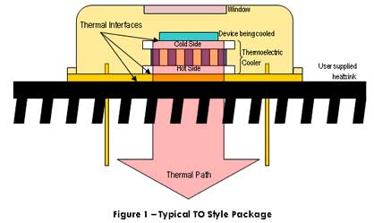
As shown in Figure 1, the thermal path is directly out of the back side of the package.

The package material is designed to provide a hermetic seal, not necessarily low thermal resistance. Since the goal is to minimize the thermal resistance in the thermal path, it is important that the heatsink be mounted directly to the back of the package (on the side where the pins protrude). Mounting to any other surface on the package increases the thermal resistance, compromises thermal performance and reduces reliability.
To reduce the thermal resistance at the heatsink/package thermal interface, the mounting surfaces must be flat and free of any pits, voids, burrs or any “casting” surface. Reducing the thermal resistance at this interface is aided by the use of an interface material (such as Thermal Compound from Wakefield Engineering, and others) between the back of the package and the heatsink. To maintain a consistent thermal path beyond five (5) years a thermal pad must be used in place of the thermal compound. This will increase the thermal resistance and thereby reduce the cooler delta T by as much as ten (10) percent but can increase the device lifetime if properly assembled and tightened when installed into the heatsink assembly. The assembly and torque are always very critical, but even more so when using a thermal pad in place of the compound paste.
The connecting pins or leads that protrude from the back of the package are hermetically sealed with a glass-filled feed through. Complete the assembly of the heatsink, including the final torque of the mounting screws prior to soldering these pins into place. Failure to mount the heatsink before soldering the pins can put stress onto the glass joint as the heatsink is tightened and lead to a hermetic seal failure. Hermetic seal failure will cause detector failure.
Avoid bending the pins. If they must be bent, use a pair of bending pliers or tweezers to isolate the bend area from the glass-filled seal. Multiple bends of these pins will lead to pin failure.
Control Electronics
External electronics are responsible for controlling the temperature and protecting the package from overheating. ΔT increases with increasing current (I) up to the point that the internal heating is greater than the heat pumping capacity. Increasing I beyond that point will heat the device, possibly to destruction. A thermistor should be used to provide feedback to controller/power supply circuitry which regulates the input power and maintains the appropriate set point temperature. A current limit must be set on the cooler power supply which is less than Imax and also prevents overheating for the model cooler being used. Note that the point at which a cooler overheats depends directly on the thermal resistance to the atmosphere and the ambient temperature.
Summary
The performance of detector packages with thermoelectric coolers is directly related to the adequate heatsinking of the package. Thermal resistance is minimized by proper heatsink selection and mounting using a thermal interface material. Overall control and protection is the responsibility of the system cooler control electronics. Proper thermal and electronic design will prevent damage and optimize the performance of the detector.
Failure to use proper handling, heatsinking, thermal path, mounting methods, and/or power limits will void any expressed or implied warranty by Opto Diode Corporation.
