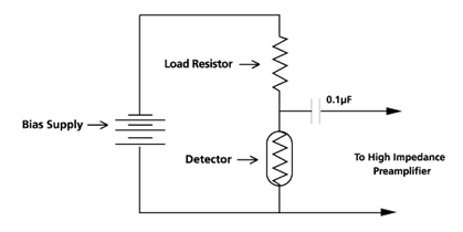
Resources: Photoconductive Infrared Detectors and Emitters - Technical Notes - Test Bias Circuit
Opto Diodes’ Test Bias Circuit
For routine detector testing, Opto Diode uses the typical bias and amplification circuit shown below. Total bias will be split between detector on load resistor based relative resistance match (or mismatch).

